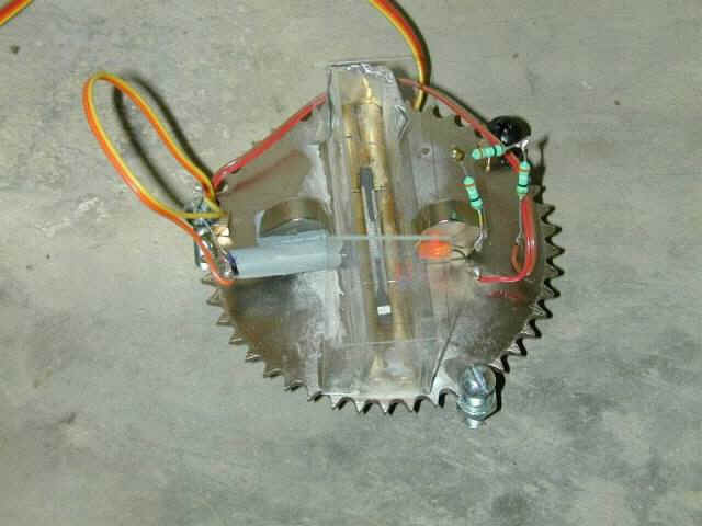

Figure 1. Showing parts arranged on 4" diameter steel cog with 3 leveling screws (nuts superglued to cog). Two rows of NIB magnets with levitating graphite in centre. CdS photo resistive cell in gray painted tube at left, LED on right, both glued to NIB magnets.
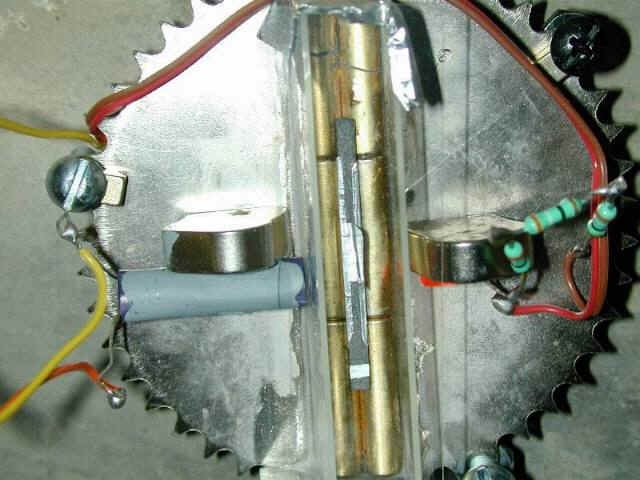
Figure 2. Shows aluminium "sail" glued to levitating graphite half-cylinder.
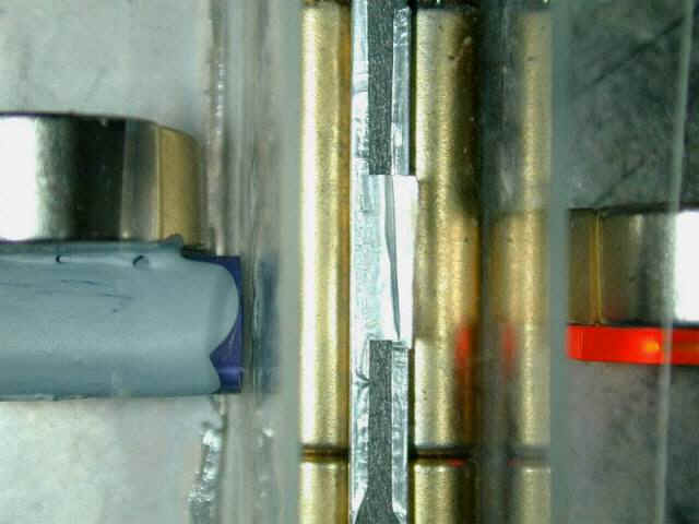
Figure 3. Close up of LED on right with light being half blocked by aluminium sail from falling on the photo resistor in the gray tube at left. Another piece of aluminium foil is wrapped around the graphite to provide damping from eddy currents. By altering the length of this piece of foil one can vary the Q of the graphite to reach critical damping.
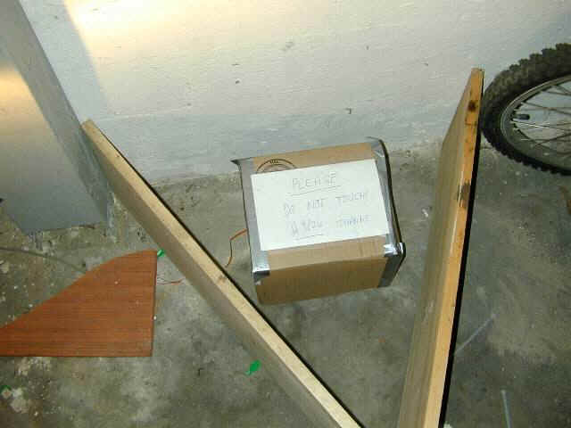
Figure 4. Cardboard box for light and draft screening.
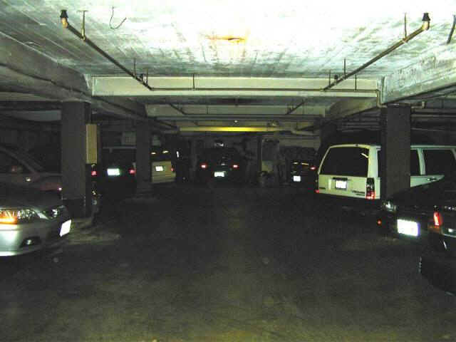
Figure 5. Seismic vault! Seismometer is on the floor at the far end on the left.
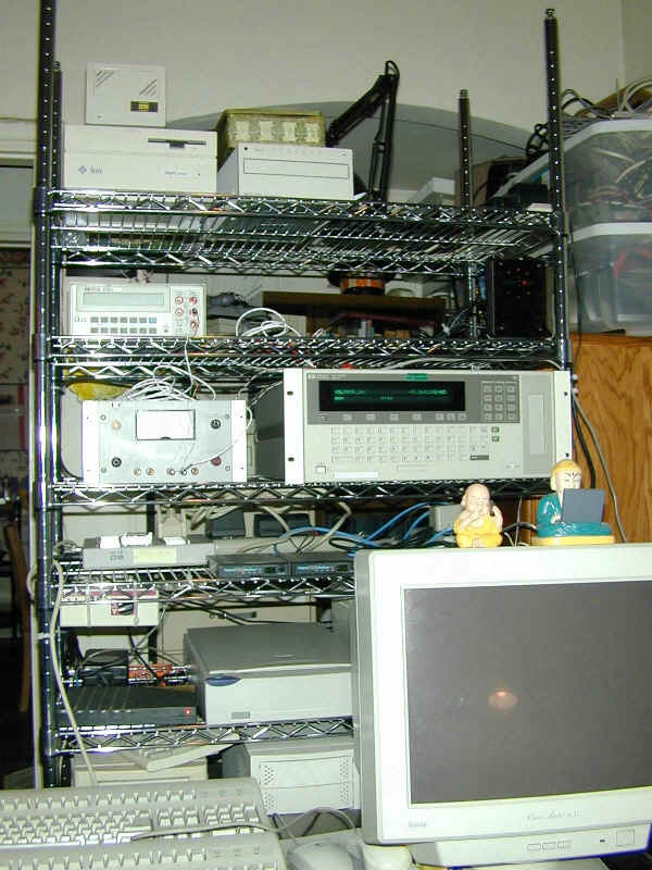
Figure 6. Data ends up here - gets read by HP75000 VXI chassis (just above Buddha on cellphone) which contains an E1326B 5.5 digit DMM. Five resistance measurements per second flow via IEE-488 interface to a computer at the bottom of the rack. Stable 4.5V DC power for the LED comes from an old HP power supply to left of 75000 chassis.